Ruler Making Machine
Brief: Create a machine that makes rulers, whose ticks are accurately spaced at every 0.5 mm over a distance ≥ 50 mm
Processes: CAD, flexure design, 3D printing
Duration: 5 weeks
Context: Pair project for ME 324: Precision Engineering
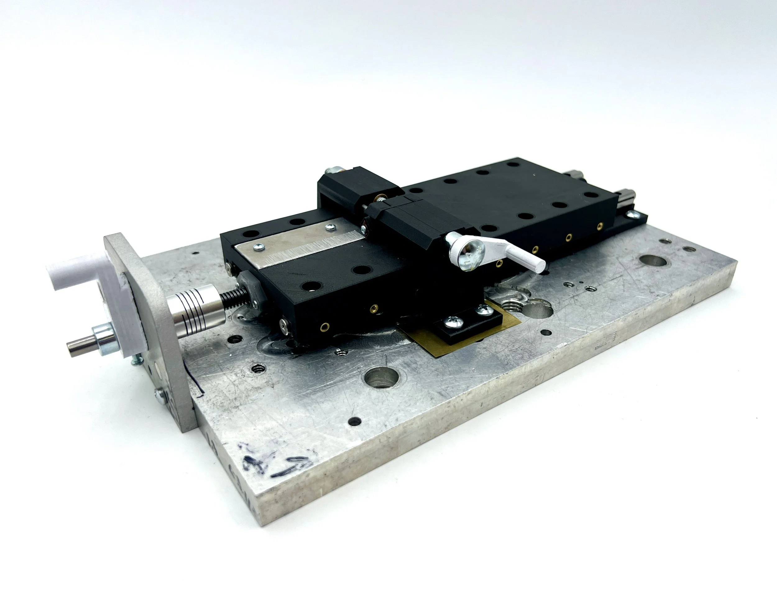
The mechanism for our ruler making machine is two decoupled actuation mechanisms, one to move in consistent increments of 0.5mm, and one to create the line mark.
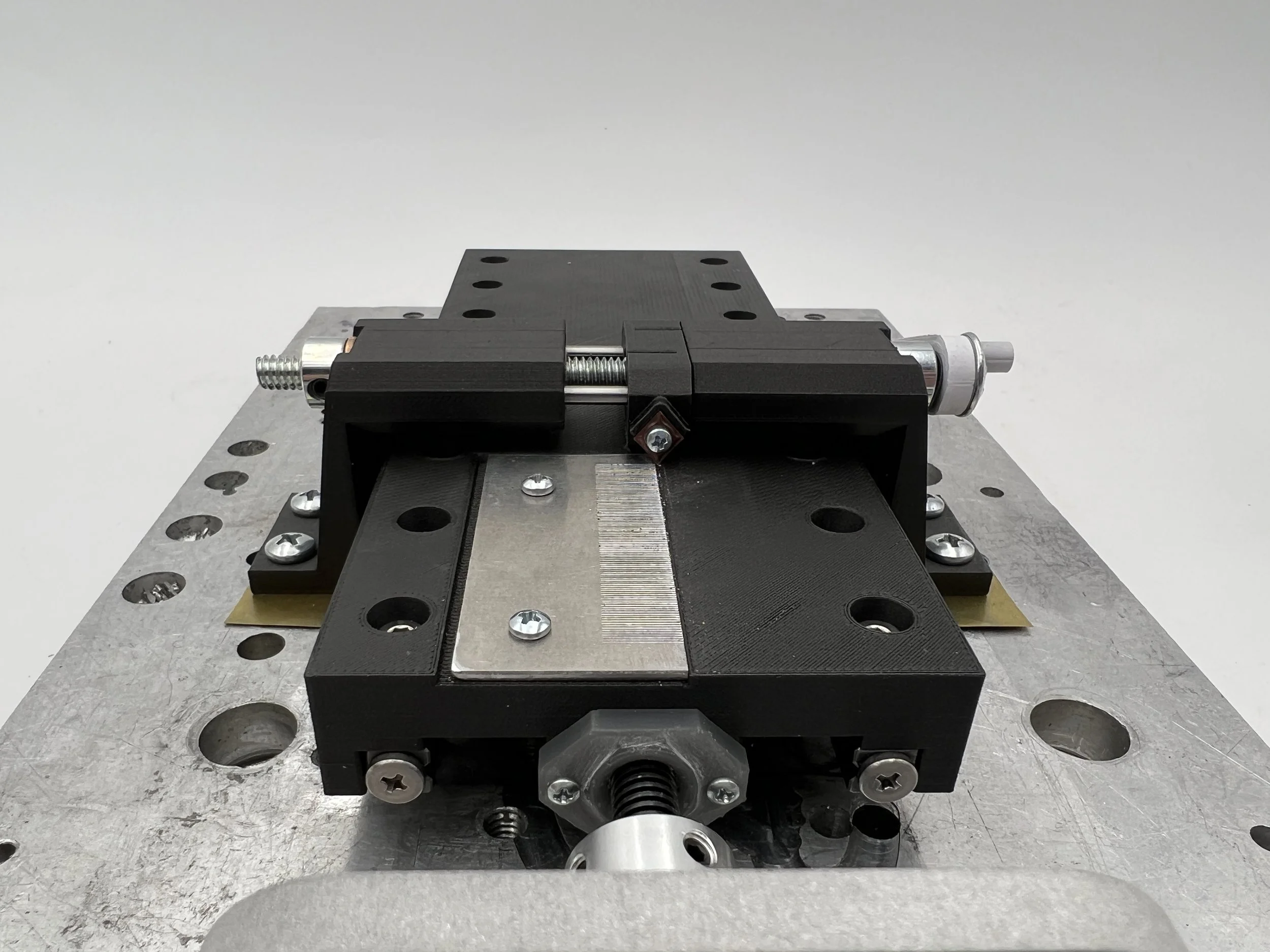
The body of the ruler making machine is a MarkForged enclosure mounted with IKO roller bearings, fastened onto a aluminum base plate. The MarkForged parts are made of Onyx, a micro carbon fiber filled nylon filament. This sturdy base was important for minimizing deformation and warpage. The IKO bearings have tight mounting specs, and if executed properly, the rollers move “without friction” and top and bottom pieces are inseparable once the bearings are mounted. It took a few prototypes in PLA to get the clearance alignment right.
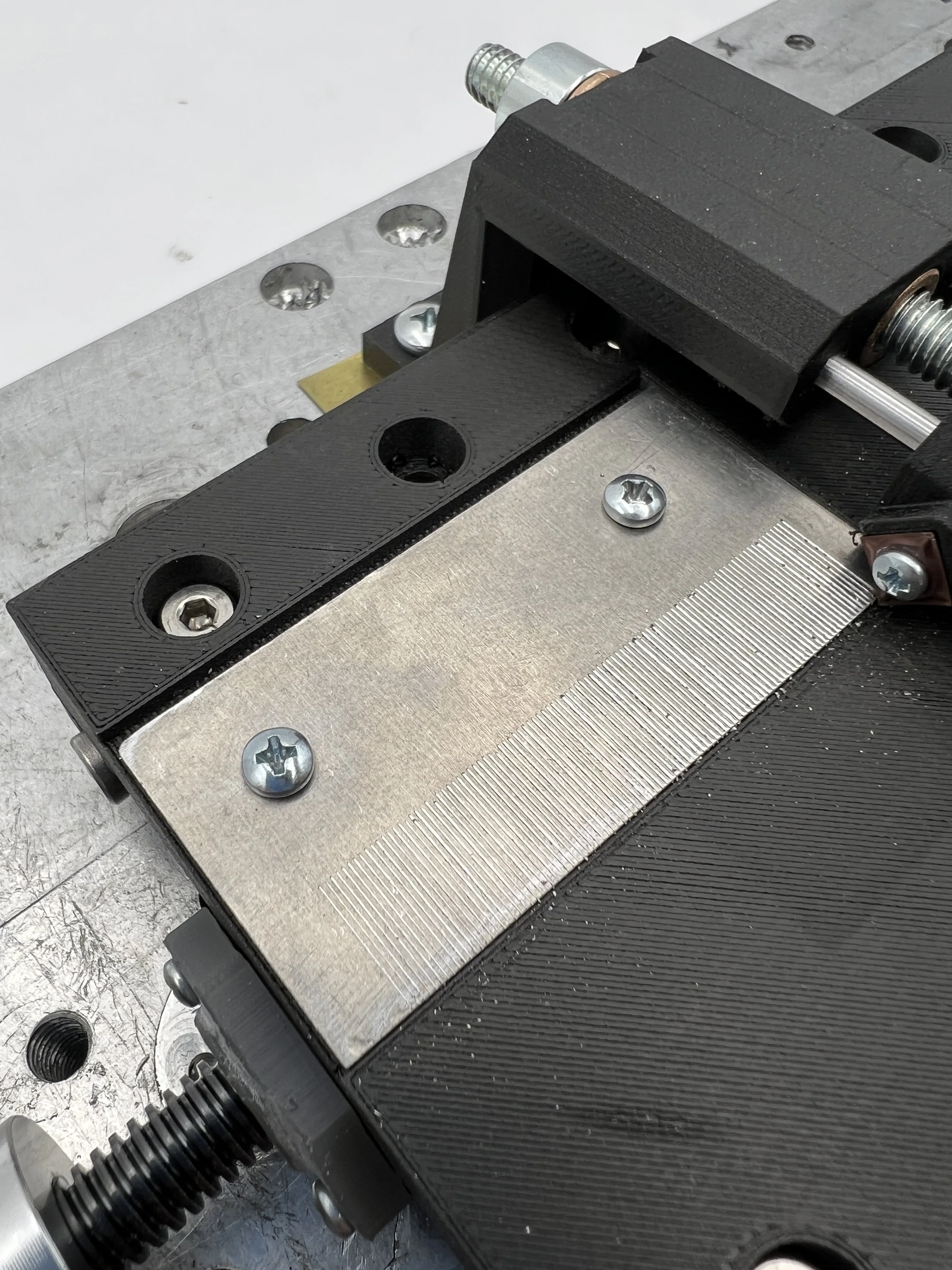
To drive the tick increment actuation, we used a 1.5mm pitch M8 lead screw with rounded trapezoidal threads as the lead screw. This pitch means that we only needed to rotate a 1/3 rotation to achieve 0.5mm translation. This thread shape is very specific, so there was only one very expensive flange nut we could use. Instead, we 3D-printed the nut specialized for our geometry using GreyPro form resin. It took some iterations to get the threading to work, and we found that oversizing the threads in XY by 8% created a smooth alignment. The lead screw was only 100mm long, and since the roller ways were longer, we needed to couple it to a D shaft to create a second point of contact. The D shaft was captured by a support created in out bottom mounting plate with an oiled flanged bushing. On the other end, the lead screw was coupled to our crank (on a D shaft) via a flexural coupling, to avoid binding. The crank was embedded with a magnet, which aligned to 3 magnets in the aluminum front support plate, placed at 120 degrees. In a previous iteration, there was a thin section of PLA to hold the magnet in place. That created a distance between the magnet in the crank and the one in the front support plate, and thus created a less strong connection. The final version of the crank removed this layer and improved alignment.
The accuracy of the cuts was subject to the flatness of the piece. We didn’t have tools to flatten the ruler blanks well, so instead we used very thin brass shims to adjust the height of the tool supports relative to a given ruler blank. The carbide cutting tip was mounted on a tool holder, which was a flexure connected at two dowels, and actuated by a 1/4-20 thread. The flexure tool holder avoided binding while the tool holder was moving along its cutting path. Potential causes for binding include non-coaxial alignment between the two dowels on which the holder rides, and inconsistent effective height of material due to being not perfectly flat. The distance between the cutting location and point of actuation was minimized to reduce Abbe error.


