PIXEL
Brief: Create many self-engaging injection molded parts
Processes: Injection Molding, CNC Milling, CAD, CAM
Duration: 4 weeks
Context: Individual project for my Injection Molding course
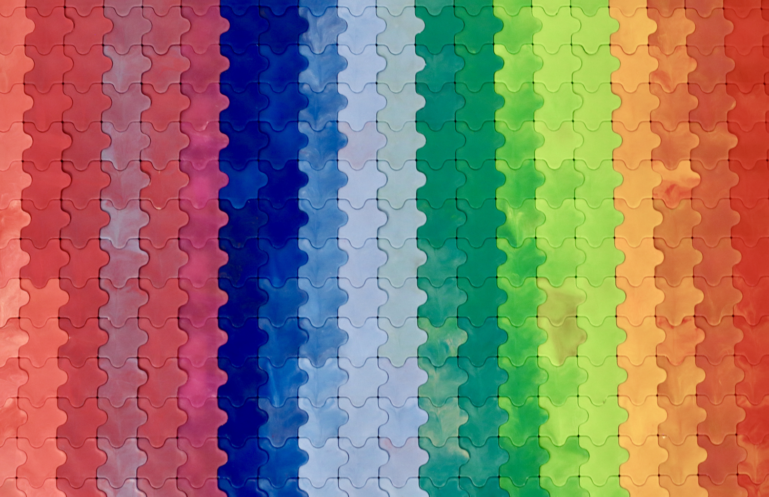
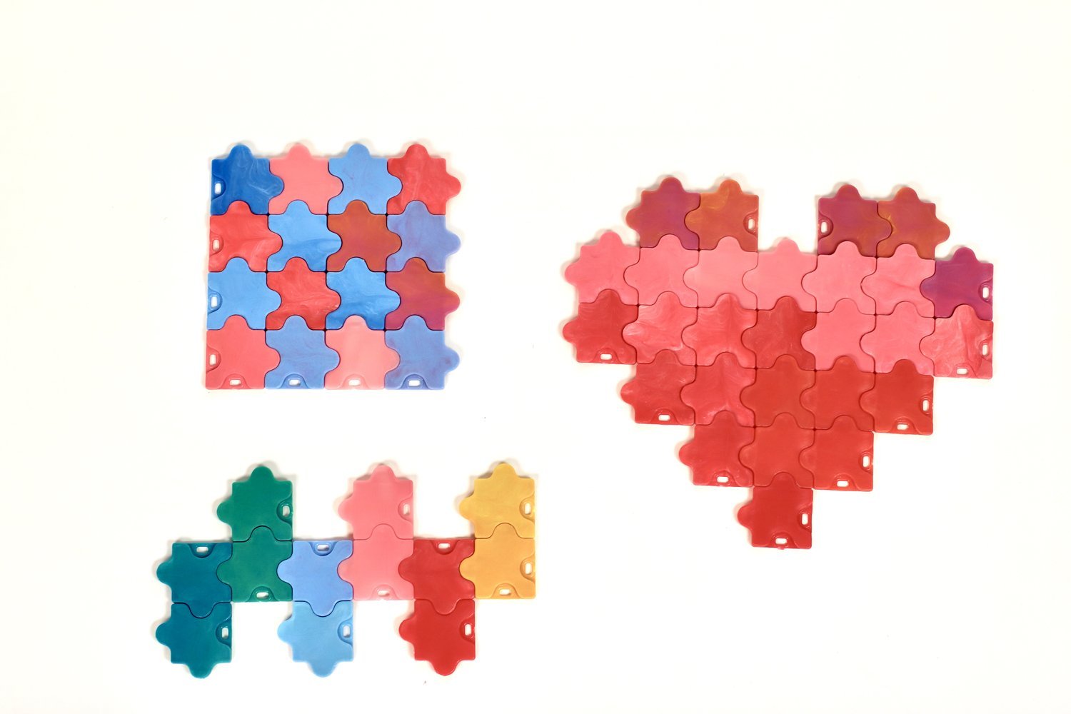
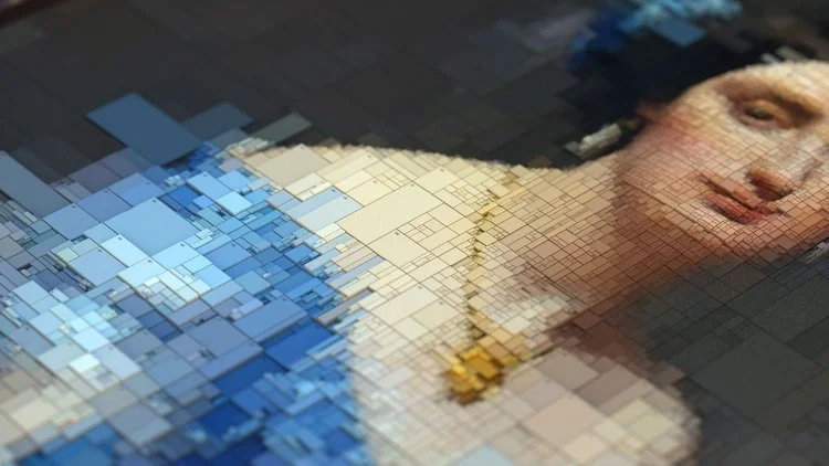
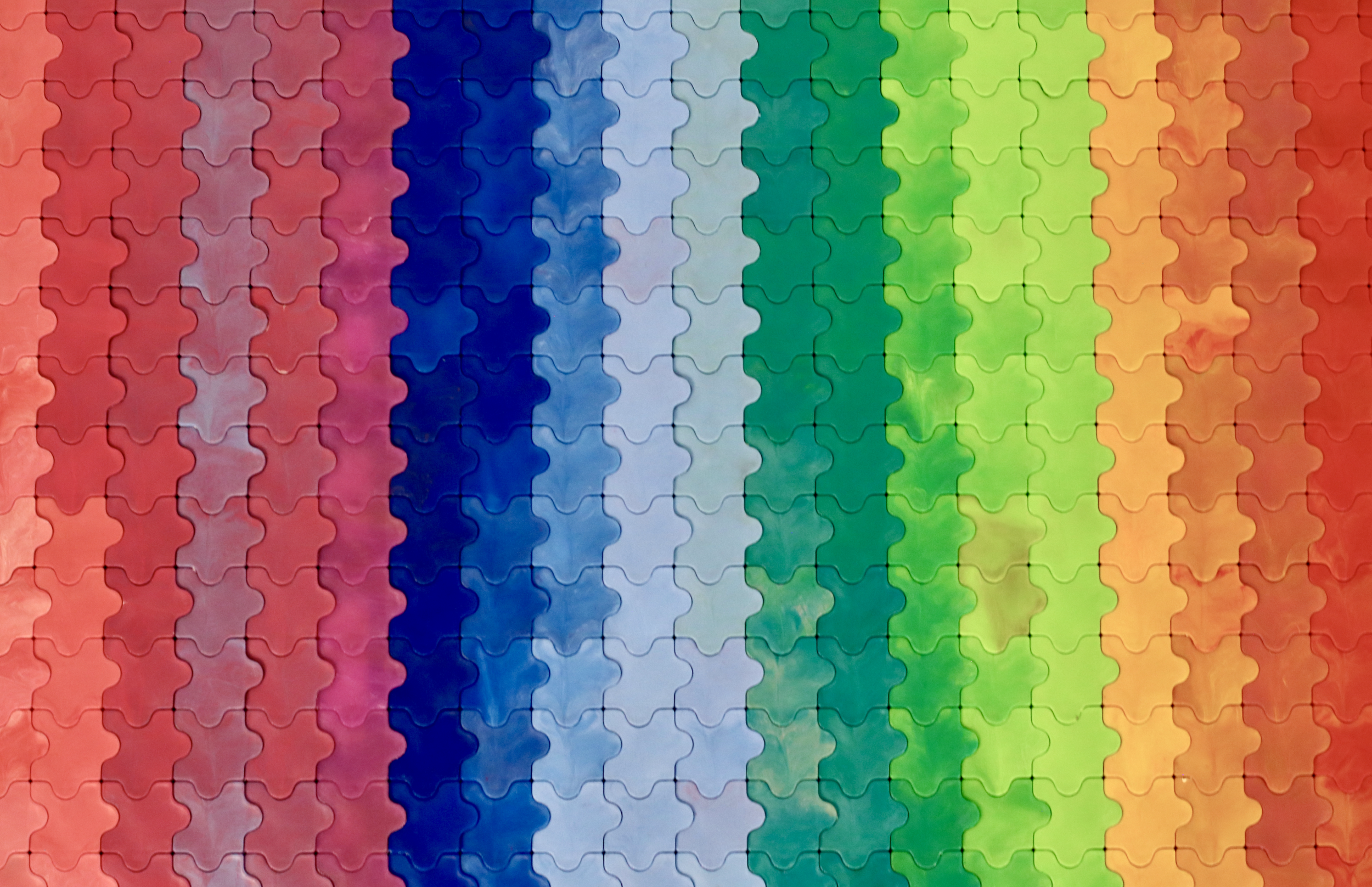
As my final project for ME 325 Making Multiples: Injection Molding, I was tasked with creating many parts that engage with each other. PIXEL is a series of infinitely-interlocking colorful puzzle pieces that allow users to create imagery. This project focused on the efficiency of creating a huge number of parts efficiently, without reducing the reliability of four interlocking features on each part. Molds for this project were created on a Haas CNC Mill, and parts were molded on an Arburg. The iterative molding process to increase part throughput included a multi-cavity mold, ejector pins, and adjustment of molding settings.
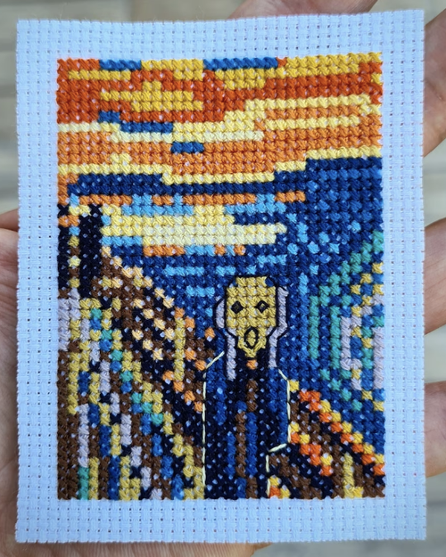
Mood Board
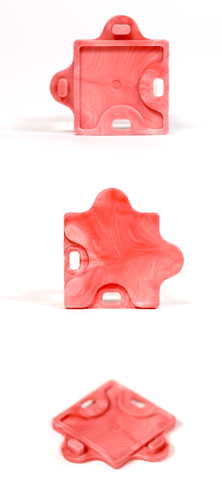
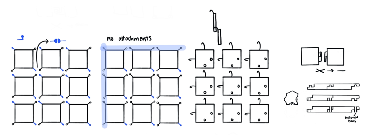
When considering the wide opportunities provided by a large quantity of parts to a user, I was drawn to creating a playful means for creativity. I explored a variety of ideas, and ultimately liked the idea of creating a singular piece that would interlock with itself in order to create any kind of visuals one desires. I played around with different interlocking mechanisms and visual designs. I decided on press four press fits per part, since this geometry allowed for only one piece, easy assembly, and no visual impact of the interlocking mechanism.
Design
Prototyping
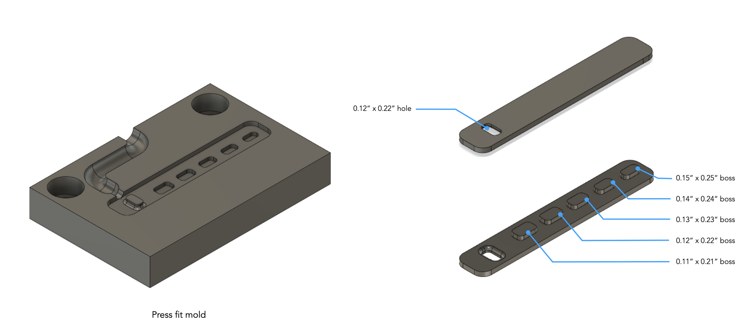
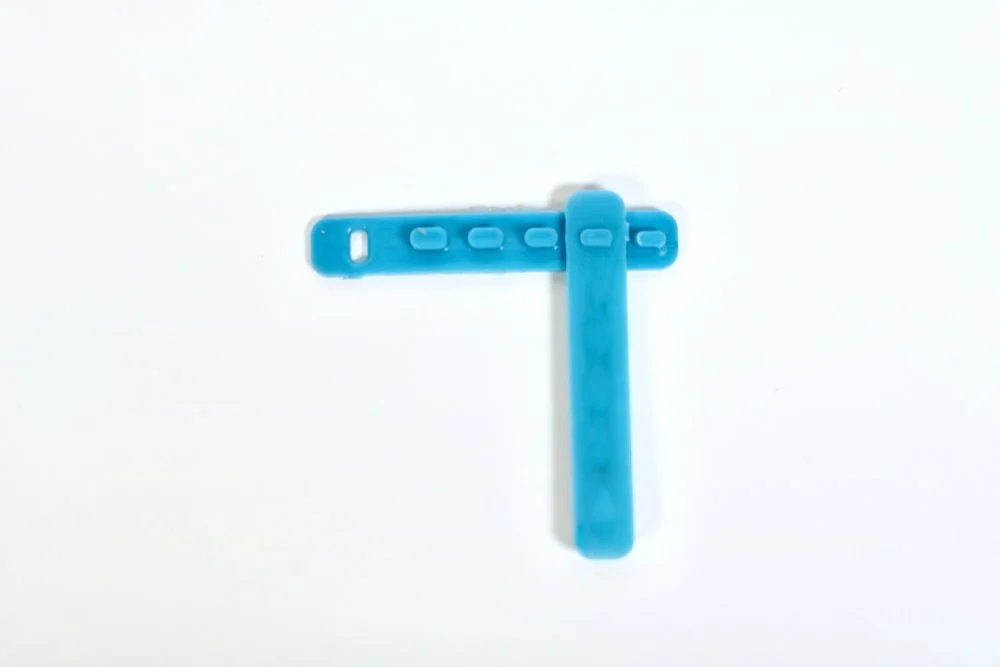
Before testing the full pieces, I wanted to focus on the snap features. At the large scale that I’m envisioning, the snap fits are critical both to the whole piece remaining intact under the weight of the 1000+ pieces and to efficiently assembling the pieces. For my prototype, I created a thin plastic piece that included the appropriately sized hole to fit my ideal piece size, with a series of bosses of varying sizes. In order to make this a one-sided mini mold, it’s not possible to create a hollowed boss. As such, I created a wide range of boss sizes to account for the varying impacts of sink.
I created a test piece that included one hole (0.12 x 0.22”) that fit nicely within the space afforded in my part, and various boss sizes, ranging from 0.11 x 0.21” to 0.15 x 0.25”. The pieces molded nicely, with only small amounts of sink. I found that the 0.12 x 0.22” boss fit the best, with the 0.13 x 0.23” being the second best option, since the boss fit but was much more challenging to remove.
Part CAD
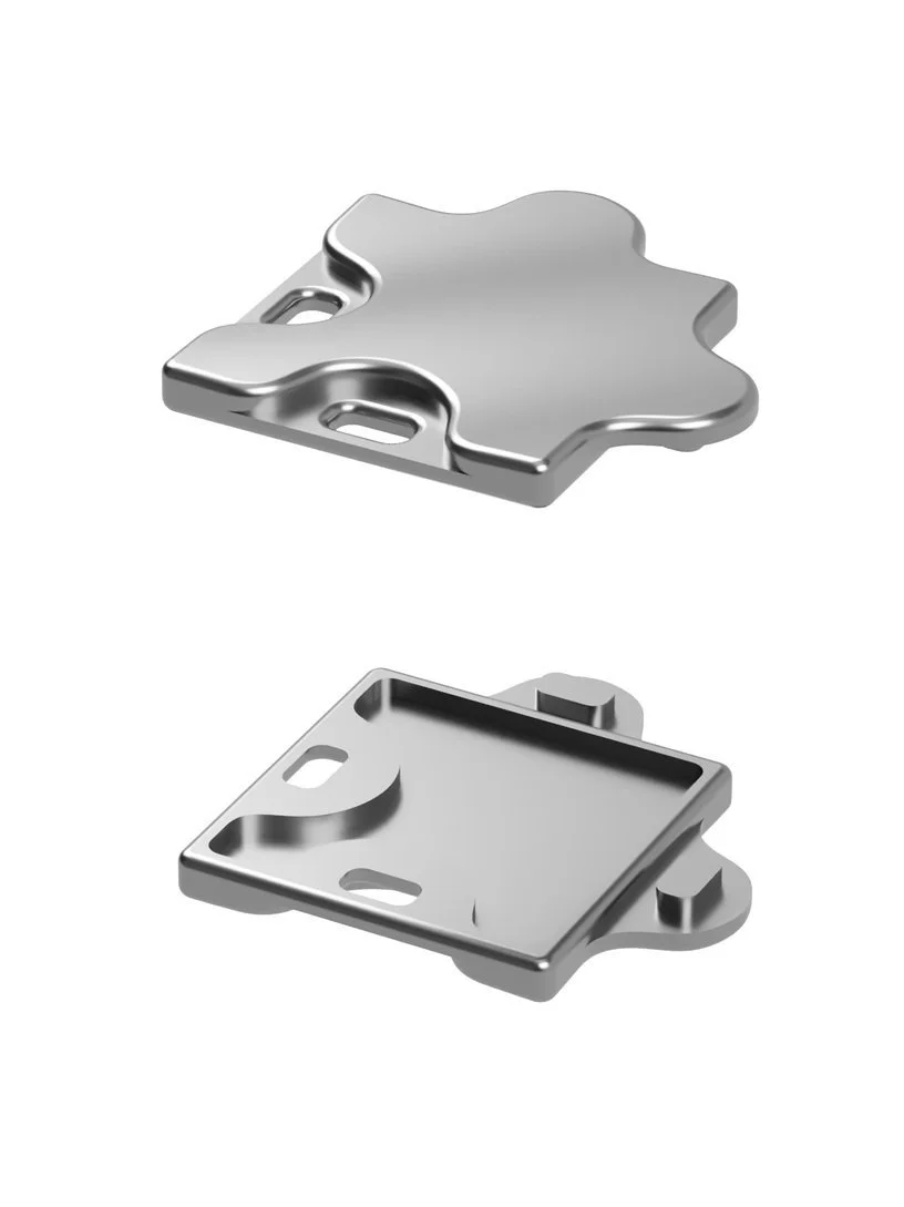
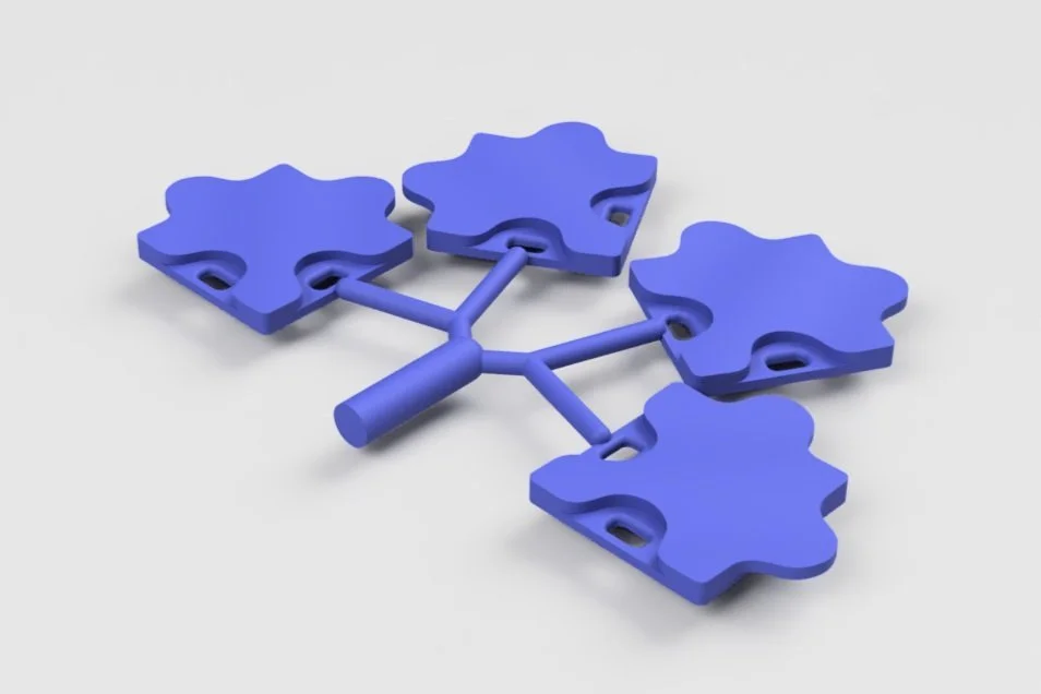
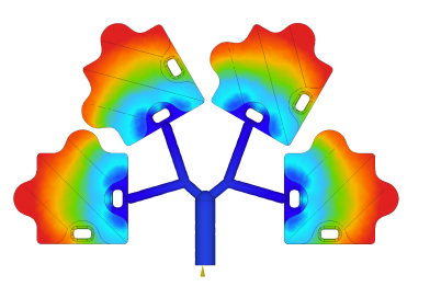
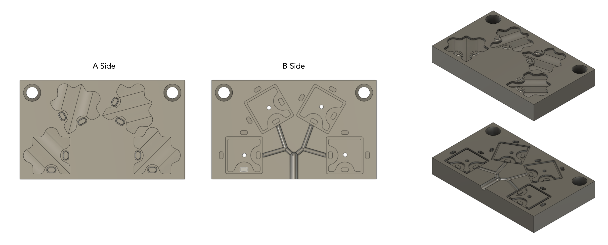
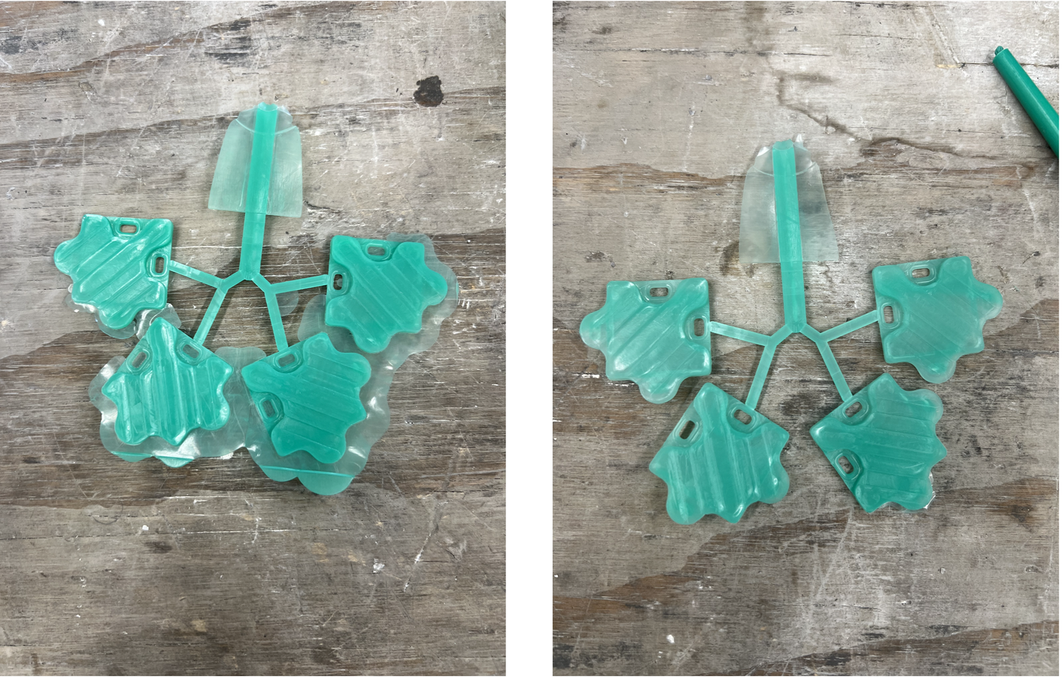
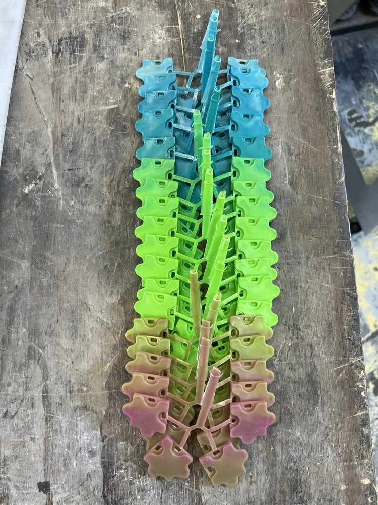
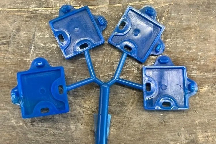
The part consists of two bosses and 2 holes each, with mirrored geometry to ensure fit. The top of the piece has a slight waves texture to give the assembled pieces more dimensionality. In order to optimize the quantity of parts per shot, I created a multi-cavity mold. The final part includes four pieces, laid out in a radial pattern to promote even flow.
Mold CAD
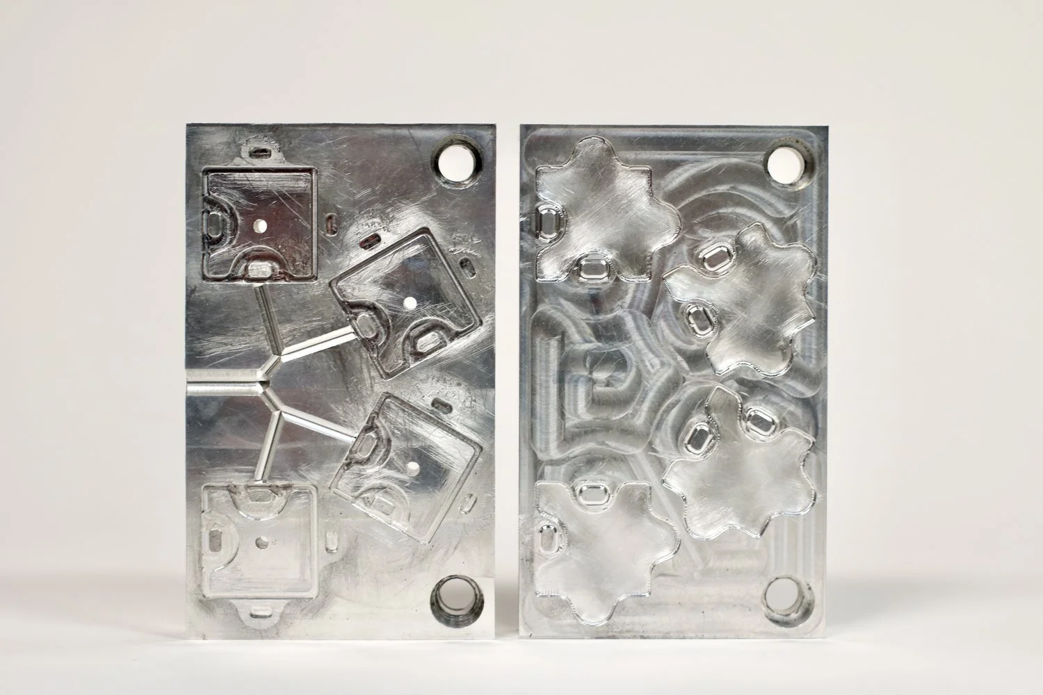
For this part, I created a two-sided mold, with a flat parting line placed at the center of the part. The full boss features were located on the B side, but the hole geometry was split between the A and B sides. The B side contained a slightly lofted hole geometry, and the B side had protruding geometry that met its respective components past the parting line. This was designed to increase efficiency of removing the pieces by reducing the surface area of contact on the B side.
CAM
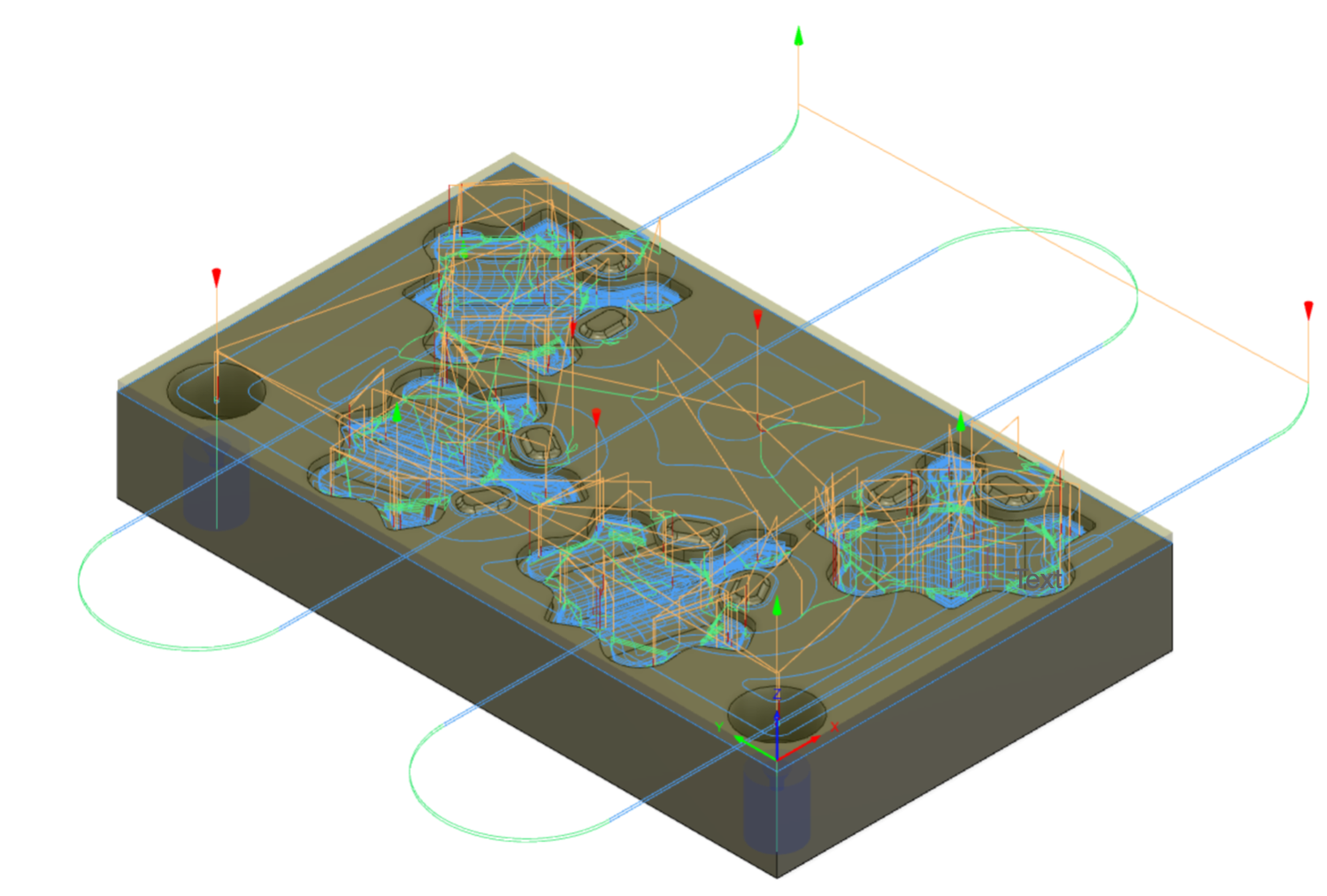
A Side
Operations:
Facing with 2” shell mill
Pocket to top surface and internal geometry with 1/2” FEM
Pocket internal geometry with 1/4” FEM
Center drilling screw holes with #2 center drill
Peck drilling screw holes with T drill
Pocket internal features with 1/8” FEM
Parallel internal curvature features with 1/16” BEM
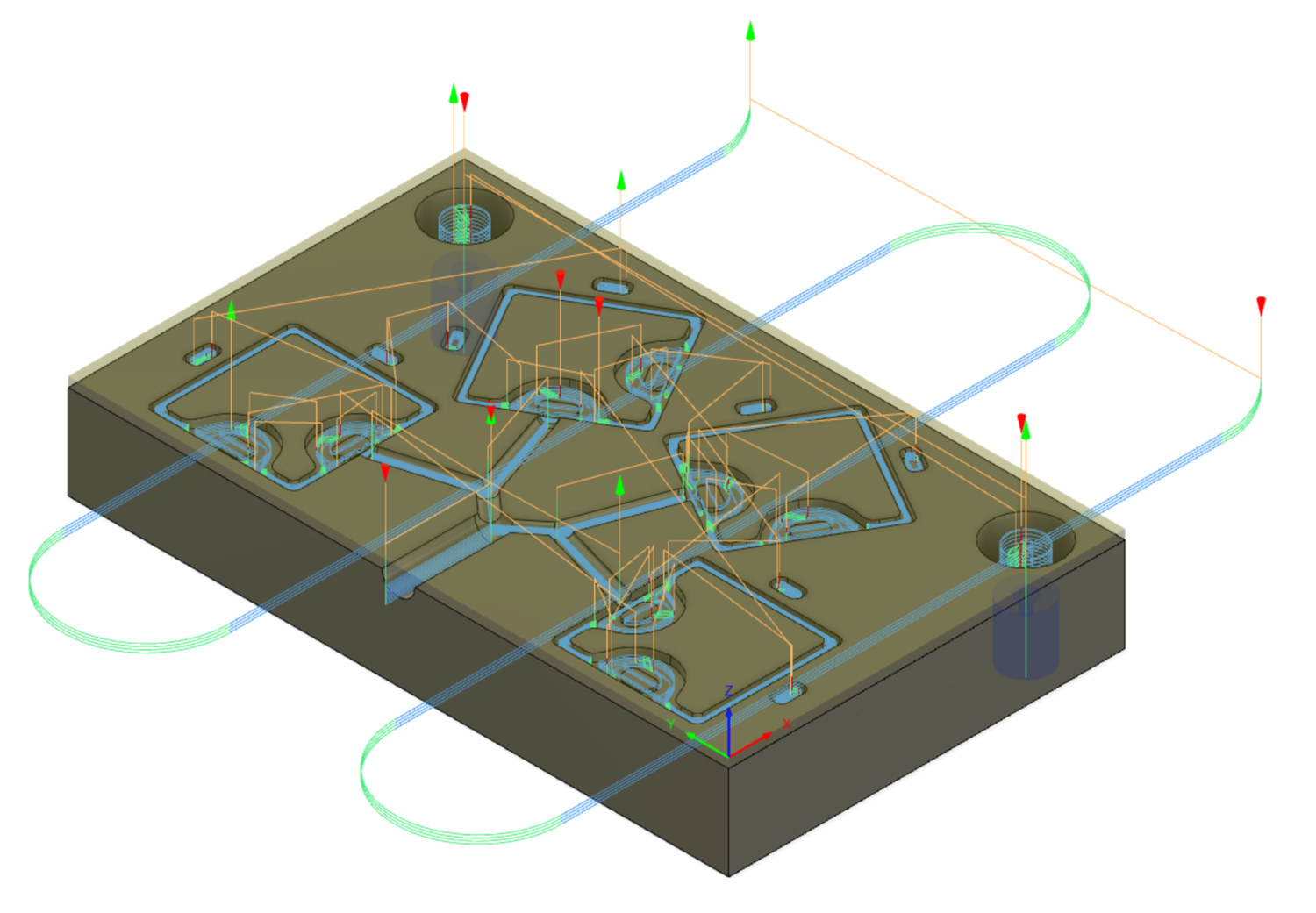
B Side
Operations:
Facing with 2” shell mill
Pocket counterbores with 1/4” FEM
Center drilling screw holes with #2 center drill
Peck drilling screw holes with T drill
Pocket internal features with 1/8” FEM
Pocket small internal features with 1/16” FEM
Trace half-round runner with 1/4” BEM
Trace half-round gates with 1/8” BEM
Machining
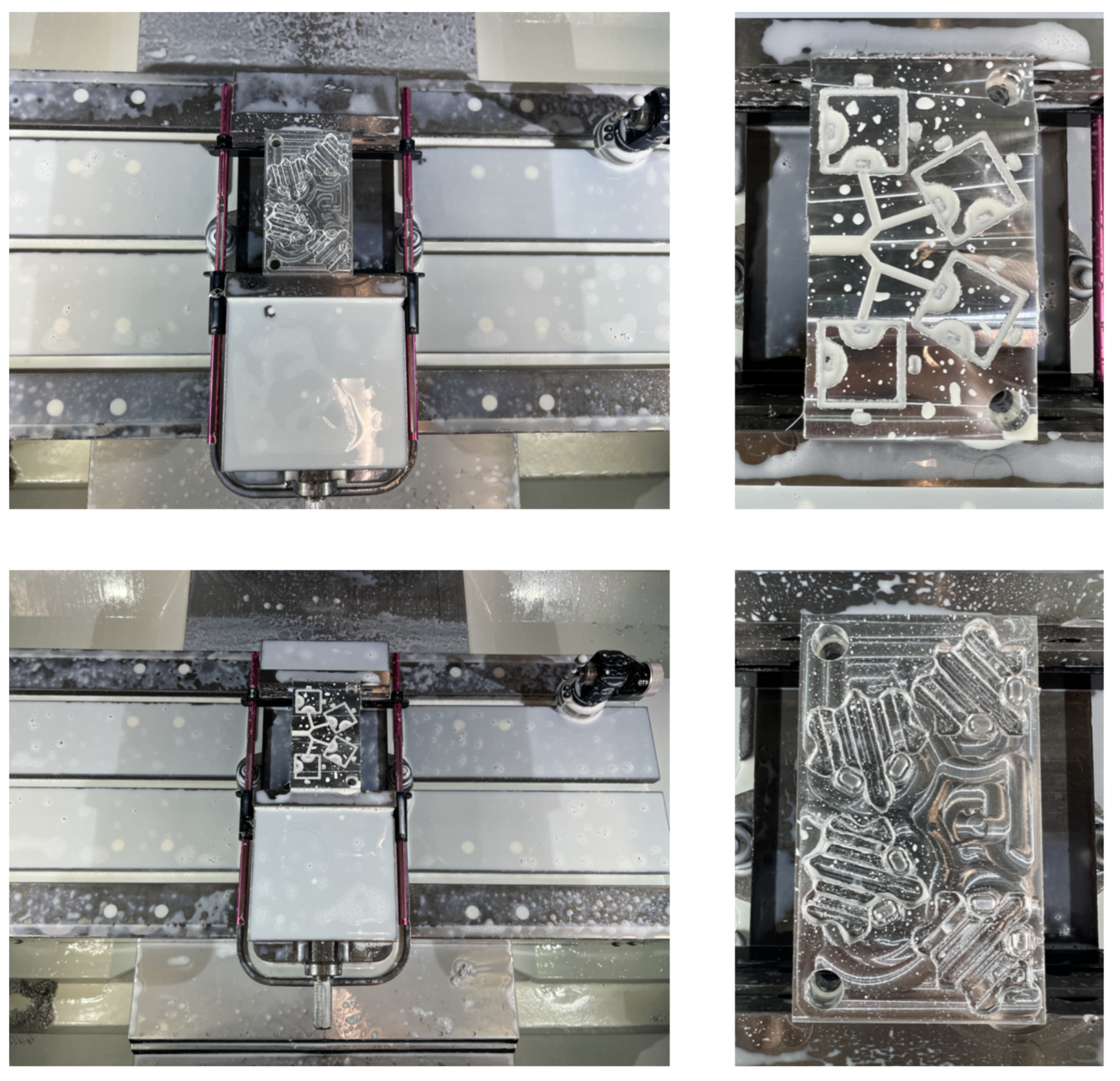
The molds were machined using a Haas VF-2 CNC Mill, made out of 6061 Aluminum. The machining steps included 3.5 hours of machining time.
A Side
The A side was machined during a two-hour machining cycle. Due to the protrusions for the hole geometry, a 1/2” FEM was used to machine to the majority of the model’s top surface. When applying the parallel finishing pass to the parts, there was a significant variance in machining time. This is most likely due to the radial orientation of the pieces, which led to performing the parallel pass in directions in which the Haas does not move as efficiently. The first time this was machined, the 1/6” BEM broke on plunge for the parallel. This was amended by machining again after molding first shots, and incorporating a 1/16” pocket before the parallel finishing passes.
B Side
The B side was machined during a one-hour machining cycle. Most of the part features were machined using a 1/8” FEM, and then a 1/16” FEM was used to clean up the geometry and cut the boss features.
First Shots
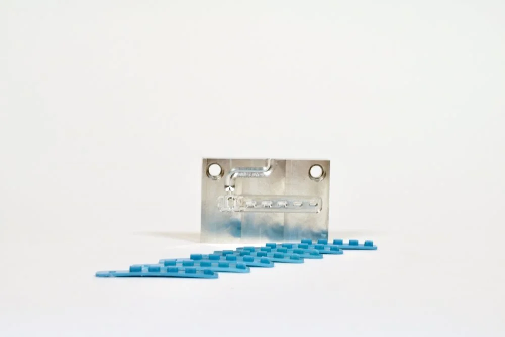
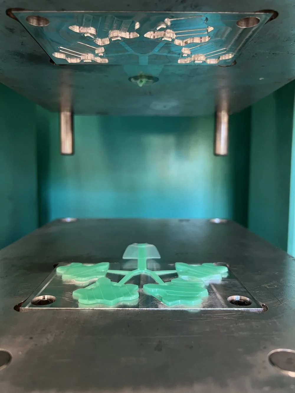
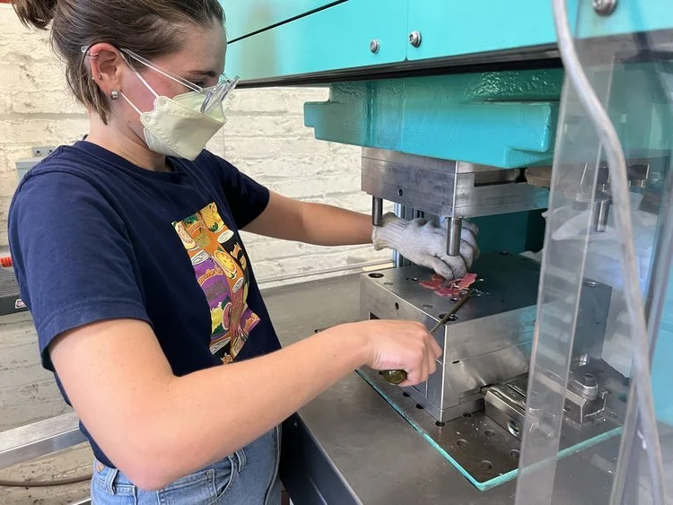
In order to test the snap fits and general molding functionality, I molded with the A side that lacked a clean surface finish. This molding process proved that the snap features work when filled properly and that the parts are challenging to remove without ejector pins. I adjusted the clamping force and holding time settings to remove flash.
Ejector Pins
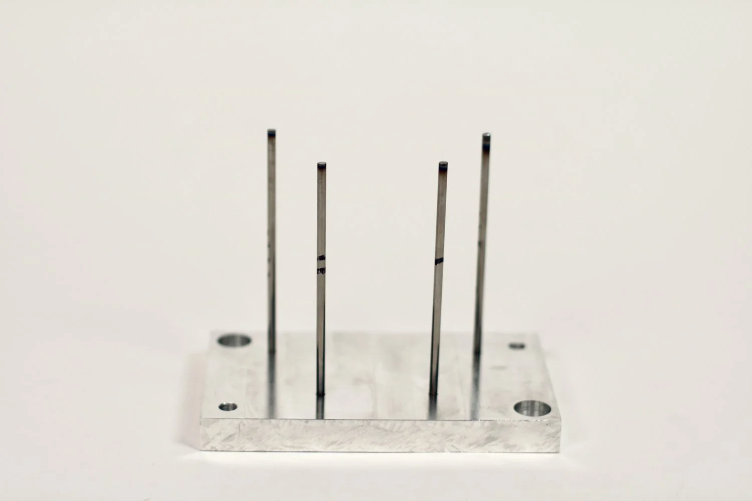
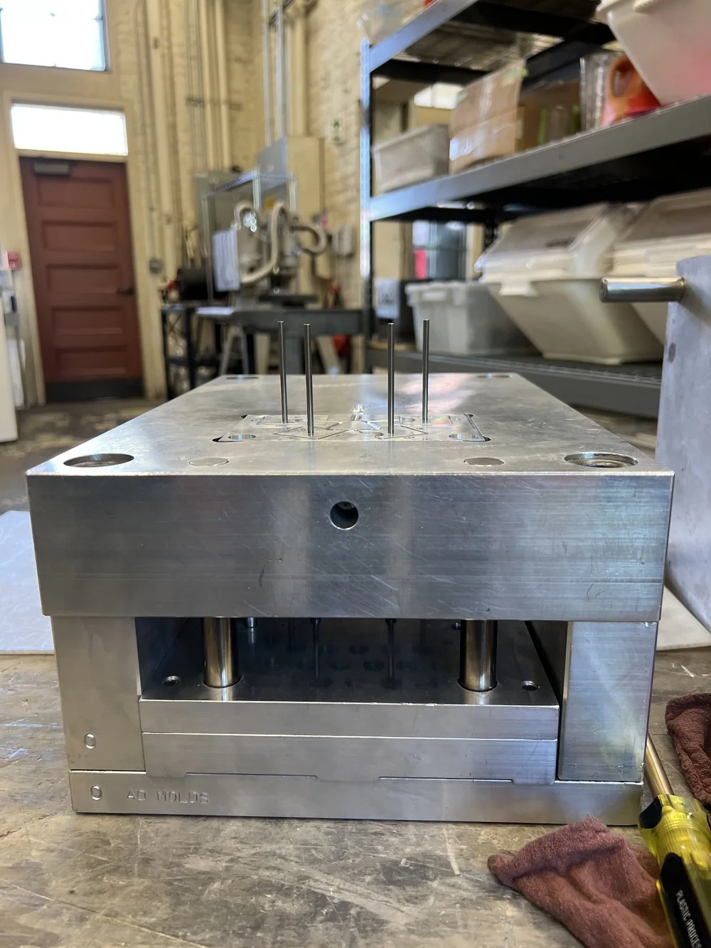
In order to efficiently mold the quantity of parts I desired, it was critical to use ejectors to decrease the part cycle time. To do so, I marked ejector pin locations based on our dimensional mold restraints, molded an ejector plate to hold the pins via a countersink, and machined holes into the B side for the pins to go through. The images below show the ejector plate, additions to the molds, and the full assembly of the mold.
Molding
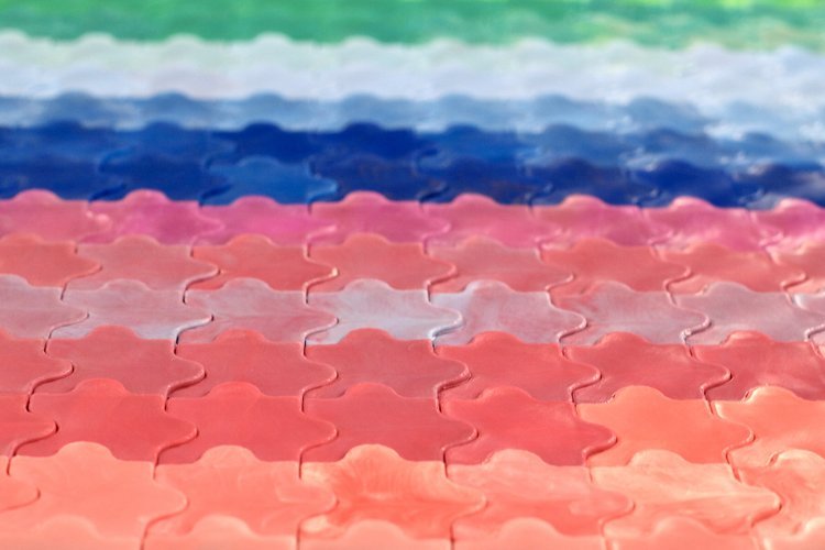
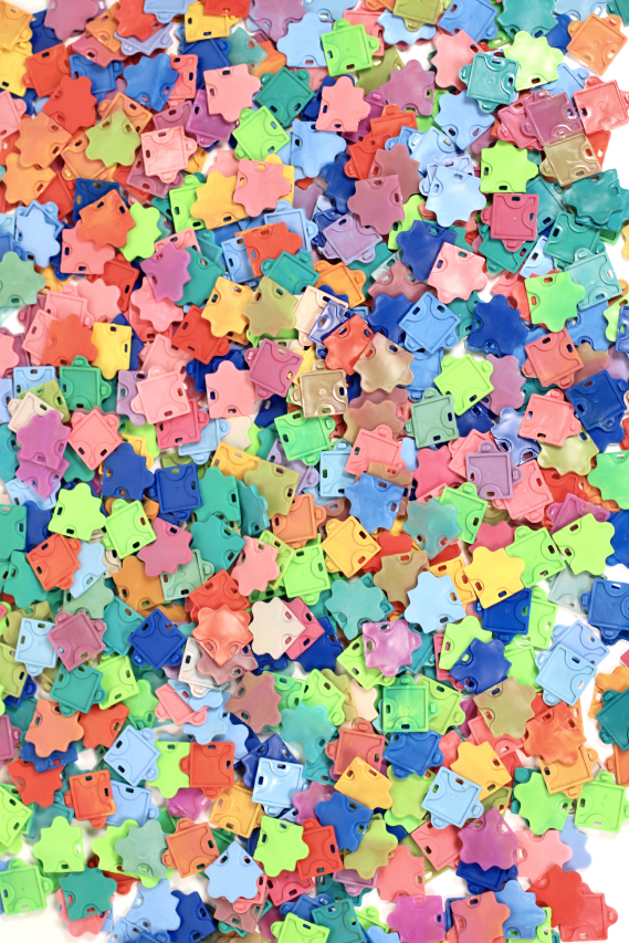
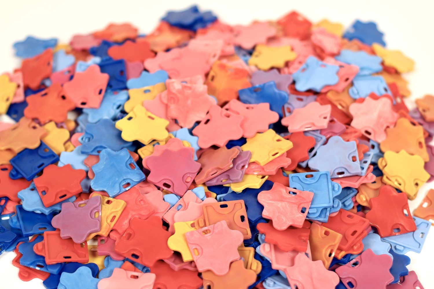
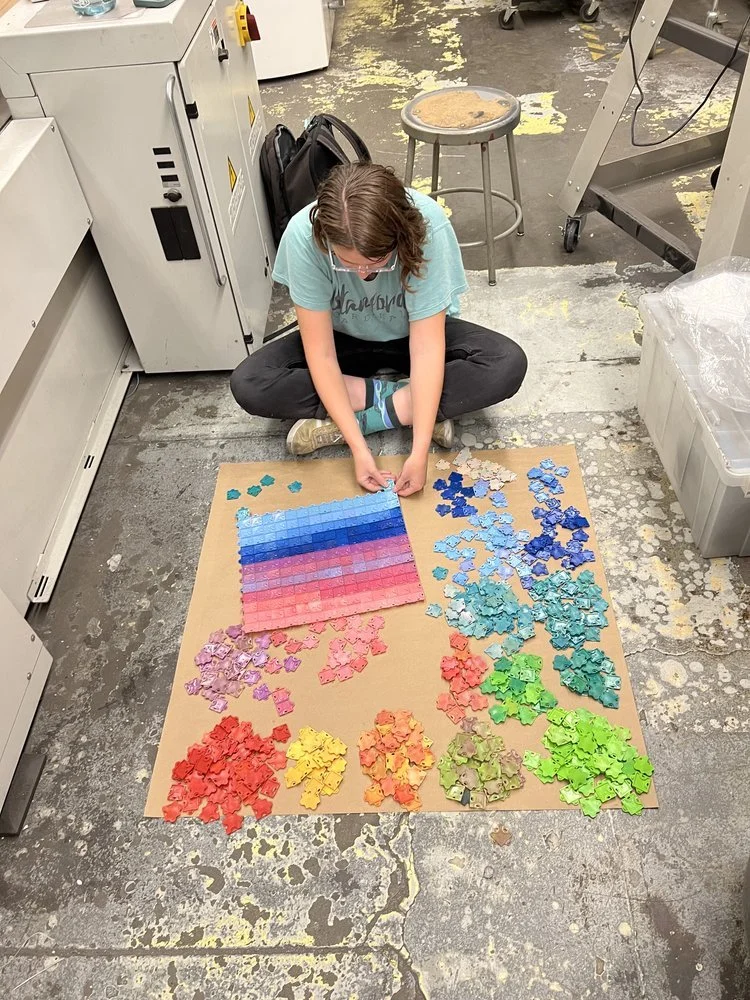
Ultimately, the parts molded very well in a large range of colors, with a total of over 400 parts total! The ejector pins helped to loosen the parts within the mold, but future iterations of this project would include additional ejector pins for each part to improve this further. Some issues that were still seen included flash around the runner, and small under-filled sections of the bosses. In order to showcase the use of this project, I assembled a large rainbow grid.
